
Hacking the Atari Flashback 2
Hacking the Atari Flashback 2
(Cartridge Port Mod)
Originally from http://www.atarimuseum.com/fb2hacks/
First thing is to remove the 5 philips head screws from underneath the console. 2 of them are underneath labels. One is the Warranty Warning tamper label, the second is in the center of the product ID label.
After you lift off the top half of the console case you can now see inside of the console and the PCB board. The Main Board is held in place by 6 screws, the Difficult Switches board is held in place by 2 screws and the Power Switch board is held in place by 2 screws. Lastly the AV cable is held in place under a tension retainer stalk with 1 screw and washer.
To assist in your Cartridge Mod additional to the console, a legend was silk-screened onto the board for easy reference. You will move a jumper wire from the IC2 ROM chip to the other side of the C4 pin. On J3 you'll need to close the jumper - you will have a choice here on whether you want to make it permanent or not, this will be discussed more later.
Remove ALL of the screws and carefully slide the board towards the front of the console and then angle it up and out out of its place. Note that the Power and Difficulty Switches all have springs between the plastic button caps and the boards, so they may spring out, keep a close eye on all three (3) of them.
So here is the Inside View of the Flashback 2 console with the PCB now removed as well as all of the switch buttons and springs.
This is the area we will be focusing on. This area of the board is where all of the connections and mods will take place to allow the use of real cartridges on the system.
Locate all 24 Cartridge pinout connections. The board is silk-screened to show pin # for each cartridge port connection, however the above image has all of the solder points highlighted in RED. Points 1, 17, 18, 19 and 23 can be a little difficult to locate and to be certain which one is which, so the above image clearly ID's all of the cartridge point points. These pads are small so take your time. Tin the solder points first to make it easier to attach the wire to each point. Have a desoldering iron on hand in case you accidentally "bridge" two solder pads together.
You will move the Black wire from IC2 to the other side of C4, then at J3 you'll need to add a jumper. I recommend you buy a single pull, single throw (SPST) Toggle switch and wire it across J3, this will allow you to enable/disable the onboard ROM chip. For the IC2 C4 connection a 3 way switch wired to the black wire on the common and one wire to the original location and an additional wire to C4 will allow you to switch from the original wire run to the C4 run. You'll need to drill open 2 holes for your two toggle switches. Its some extra work, but worth it since you'll be able to continue using the 40 built in games and then switch to using cartridges when needed.
Soldering iron (15-20 watt), thin solder will be needed along with wire cutters, I recommend a desoldering tool and some solder braid to help out if you make a mistake. A desktop set of PCB board holders is a good tool to have on hand when doing this kind of work. Make sure you have good bright lighting to work by.
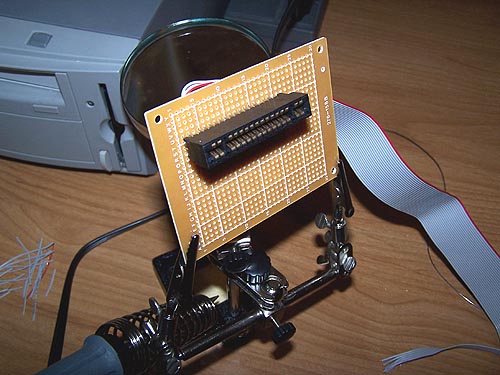
You'll need a PC component board which is available at most Radio Shacks. A flat ribbon cable is my recommendation for you wire connections, it'll be cleaner and easier to work with, the wire is general 28-32guage so stripping the wires is a very delicate procedure, take your time.
The 2600 cartridge connector and (Optional) cartridge guide can be obtained from:
B&C Atari Sales & Service - www.myatari.com
Best Electronics - Atari Parts & Sales - www.best-electronics-ca.com
I would really recommend the plastic guide if you plan to make a really presentable cosmetic mod to the top of the console case to allow you to place cartridges into the slot. You'll need to trim the PC Component Board and make the appropriate drill holes so you can screw the PC component board the underside of the Cartridge Guide Plastic. (IMPORTANT NOTE - Be sure you do this BEFORE soldering the cartridge connector to the PC Component board so you have the correct height of the cartridge connector underneath the Cartridge Guide Plastic.) You can use an Atari 7800 Cartridge connector as well, but you'll need the 7800 cartridge guide plastic.
Atariage.com maintains the most up to date Atari 2600 FAQ. In this FAQ you will find the cartridge connector Pinouts for the 2600. After you solder your Cartridge Connector for the PC Component Board. Mark the 4 corners of the underside of the cartridge pins 1 12 13 24 So you'll know where your going. I split the ribbon cable down in half about 4 inches of so. One side was pins 1 through 12, then continuing I soldered 13 through 24.
I would recommend you use a voltmeter and double check all of the pins the end of the ribbon cable and make sure you have a solid connection. Next thing, put the meter (set to check for a closed circuit with audio beep) and put one lead onto pin 1, then with the lead and go from pin 2 through 24, if not beep, then move to pin 2 and go from 3 to 24 and repeat. This will help you make certain you did bridge any of the cartridge pins together by accident. If you get a beep and a closed circuit with 2 pins, check them and correct as needed.
When attaching each wire to the PCB start at 1 and work your way across the ribbon cable, you'll need to trim the insulation about no more then 1/16th of inch for each wire. Again double-check for shorts/bridges and correct if needed.
Set your Toggle switches to the 40 in 1 ROM and test the unit to see if the Menu appears, POWER OFF, now switch the toggle switches and insert a cartridge and Power up, you are now using original 2600 cartridges. If the screen is black or filled with garbage you may have the cartridge backwards, POWER OFF, turn it around and try again. If your game cart is not working, double-check your connections and the order of your wires to the cartridge connector pins. If its still not working, try your console with a cart like Combat, Breakout, Adventure, something simple and ensure you are not encountering any issues.
I've only done the electronics side, I haven't had time to do the cosmetic version yet. Basically you'll need to make an opening with a dremel or other hobbyist cutting tool on the top center of the console and slide the Cartridge Guide plastic into place, it has a lip around it so its sit flush, apply some plastic bonding glue to permanently attach it. Now put the cartridge PC board into place under it, screw in the two retaining screws to secure the cartridge board to the plastic guide, and carefully reassemble your Flashback 2 console. If you did the toggle switch mod, slide the switch masts through 2 holes in the back bottom of the console plastic and secure the holding nuts into place and tighten. Once your console is assembled, test it with the toggle switches in the 40 in 1 ROM position and make sure the normal Flashback Menu appears, if all is well, now POWER OFF, switch the toggle switches and test a cartridge.
One last note - I have NOT tested the console with a multicart or Maxi26 or any of the more power-hungry cartridges, so try those at your own additional risk. Happy hacking/modding!!!