


How to Draw a Playfield
;
; How to Draw A Playfield.
; by Nick Bensema 6:35PM 9/10/98
;
; Atari 2600 programming is different from any other kind of programming
; in many ways. Just one of these ways is the flow of the program.
;
; Since the CPU must hold tha TIA's hand through all graphical operations,
; the flow ought to go like this:
;
; Clear memory and registers
; Set up variables
; Loop:
; Do the vertical blank
; Do game calculations
; Draw screen
; Do more calculations during overscan
; Wait for next vertical blank
; End Loop.
;
; What I will do is create an outline, and explain everything I can.
; This program will display "HELLO" and scroll it down the screen.
;
; In writing this program, I will take the opportunity to show you
; how a few simple modifications can completely change a program's
; appearance or behavior. I will invite you to comment out a few
; lines of code, and alter others, so that you can observe the results.
;
; I will be using DASM for now. Conversion to A65 should be trivial.
;
processor 6502
include vcs.h
org $F000
Temp = $80
PlayfieldY = $90
Start
;
; The 2600 powers up in a completely random state, except for the PC which
; is set to the location at $FFC. Therefore the first thing we must do is
; to set everything up inside the 6502.
;
SEI ; Disable interrupts, if there are any.
CLD ; Clear BCD math bit.
;
; You may feel the need to use the stack, in which case:
;
LDX #$FF
TXS ; Set stack to beginning.
;
; Now the memory and TIA registers must be cleared. You may feel the
; need to write a subroutine that only clears out a certain section of
; memory, but for now a simple loop will suffice.
;
; Since X is already loaded to 0xFF, our task becomes simply to ocunt
; everything off.
;
LDA #0
B1 STA 0,X
DEX
BNE B1
;
; The above routine does not clear location 0, which is VSYNC. We will
; take care of that later.
;
; At this point in the code we would set up things like the data
; direction registers for the joysticks and such.
;
JSR GameInit
;
; Here is a representation of our program flow.
;
MainLoop
JSR VerticalBlank ;Execute the vertical blank.
JSR CheckSwitches ;Check console switches.
JSR GameCalc ;Do calculations during Vblank
JSR DrawScreen ;Draw the screen
JSR OverScan ;Do more calculations during overscan
JMP MainLoop ;Continue forever.
;
; It is important to maintain a stable screen, and this routine
; does some important and mysterious things. Actually, the only
; mysterious part is VSYNC. All VBLANK does is blank the TIA's
; output so that no graphics are drawn; otherwise the screen
; scans normally. It is VSYNC which tells the TV to pack its
; bags and move to the other corner of the screen.
;
; Fortunately, my program sets VBLANK at the beginning of the
; overscan period, which usually precedes this subroutine, so
; it is not changed here.
;
VerticalBlank ;*********************** VERTICAL BLANK HANDLER
LDX #0
LDA #2
STA WSYNC
STA WSYNC
STA WSYNC
STA VSYNC ;Begin vertical sync.
STA WSYNC ; First line of VSYNC
STA WSYNC ; Second line of VSYNC.
;
; But before we finish off the third line of VSYNC, why don't we
; use this time to set the timer? This will save us a few cycles
; which would be more useful in the overscan area.
;
; To insure that we begin to draw the screen at the proper time,
; we must set the timer to go off just slightly before the end of
; the vertical blank space, so that we can WSYNC up to the ACTUAL
; end of the vertical blank space. Of course, the scanline we're
; going to omit is the same scanline we were about to waste VSYNCing,
; so it all evens out.
;
; Atari says we have to have 37 scanlines of VBLANK time. Since
; each scanline uses 76 cycles, that makes 37*76=2888 cycles.
; We must also subtract the five cycles it will take to set the
; timer, and the three cycles it will take to STA WSYNC to the next
; line. Plus the checking loop is only accurate to six cycles, making
; a total of fourteen cycles we have to waste. 2888-14=2876.
;
; We almost always use TIM64T for this, since the math just won't
; work out with the other intervals. 2880/64=44.something. It
; doesn't matter what that something is, we have to round DOWN.
;
LDA #44
STA TIM64T
;
; And now's as good a time as any to clear the collision latches.
;
LDA #0
STA CXCLR
;
; Now we can end the VSYNC period.
;
STA WSYNC ; Third line of VSYNC.
STA VSYNC ; (0)
;
; At this point in time the screen is scanning normally, but
; the TIA's output is suppressed. It will begin again once
; 0 is written back into VBLANK.
;
RTS
;
; Checking the game switches is relatively simple.
;
; It just so happens that I'm not going to check any game switches
; here. I'm just going to set up the colors, without even checking
; the B&W switch! HA!
;
CheckSwitches ;*************************** CONSOLE SWITCH HANDLER
LDA #0
STA COLUBK ; Background will be black.
RTS
;
; Minimal game calculations, just to get the ball rolling.
;
GameCalc ;******************************* GAME CALCULATION ROUTINES
INC PlayfieldY ;Inch up the playfield
RTS
;
; This is the scariest thing I've done all month.
;
DrawScreen ;**************************** SCREEN DRAWING ROUTINES
LDA INTIM
BNE DrawScreen ; Whew!
STA WSYNC
STA VBLANK ;End the VBLANK period with a zero.
;
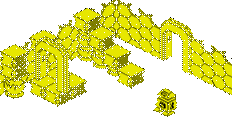
; Now we can do what we need to do. What sort of playfield do
; we want to show? A doubled playfield will work better than
; anything if we either want a side scroller (which involves some
; tricky bit shifting, usually) or an asymmetrical playfield (which
; we're not doing yet). A mirrored playfield is usually best for
; vertical scrollers. With some creativity, you can use both in your
; game.
;
; The "score" bit is useful for drawing scores with playfield graphics
; as Combat and other early games do. It can also create a neat effect
; if you know how to be creative with it. One useful application of
; score mode would be always having player 1 on the left side, and
; player 0 on the right side. Each player would be surrounded in the
; opposite color, and the ball graphic could be used to stand out
; against either one. On my 2600jr, color from the right side bleeds
; about one pixel into the left side, so don't think it's perfect.
; It's really far from perfect because PC Atari does not implement
; it at all; both sides appear as Player 0's color. A26 does, though.
;
; To accomodate this, my routine puts color values into
; COLUP0 for the left side, and COLUP1 for the right side. Change
; the LDA operand to 0 or 1 to use the normal system. The code in
; the scanning loop accounts for both systems.
;
LDA #2
STA CTRLPF
;
; Initialize some display variables.
;
;There aren't any display variables!
;
; I'm going to use the Y register to count scanlines this time.
; Realize that I am forfeiting the use of the Y register for this
; purpose, but DEC Zero Page takes five cycles as opposed to DEY's
; two, and LDA Zero Page takes three cycles as opposed to TYA's two.
;
; I'm using all 191 remaining scanlines after the WSYNC. If you
; want less, or more, change the LDY line.
;
; This is a decremental loop, that is, Y starts at 191 and continues
; down to 0, as do all functions of Y such as memory locations, which
; is why the graphics at the end of this file are stored "bottom-up".
; In a way, one could say that's how the screen is drawn. To turn this
; into an incremental loop, change the number to 65 (255-191) and change
; the DEY at the end ot the scanning loop to INY.
;
LDY #191
;
; Okay, now THIS is scary. I decided to put the bulk of my comments
; BEFORE the code, rather than inside it, so that you can look at the
; code all at once.
;
; This routine came out surprisingly clean. There are no branches,
; and most updates are made even before PF0 becomes visible at cycle 23,
; even though PF1 and PF2 don't become visible until, by my estimate,
; cycles 29 and 40, respectively. We could use this time to get player
; shape and colors from temp variables and sneak them in, but that's
; another file. I put less-than signs in there to demonstrate that
; each register is changed before the "deadline cycle" at which point
; the changes would not completely appear on the current scanline.
;
; The playfield will only be moved up every 4 scanlines, so it doesn't look
; squished. I could have updated it every 2 scanlines, and that would have
; saved two cycles. I could have saved another two cycles by having it
; change EVERY scanline. Comment out one or both of the ASL's to see what
; this would look like. I realize that it updates the PF registers whether
; it needs it or not, but it would be pointless to branch around these
; updates. Better to know you're wasting cycles and have them counted
; than to get unlucky and have your code spill into the next scanline
; every time too many things get updated.
;
; This is going to be a moving playfield. For a stationary playfield,
; comment out the SEC and SBC lines. That's probably what most of you all
; are going to want, anyway. And for a really good moving playfield,
; like in River Raid or Vanguard, you'll need slightly more interesting
; code than I'm prepared to provide.
;
; I also could have made the playfield graphic 16 bytes high, or 32, or 64,
; by changing only my data and the AND line. AND can serve as a modulus
; for any power of two (2^n) up to 128, by ANDing a byte with that number
; minus one ( (2^n)-1 ). 8 bytes * every 4 scanlines == 32, which is
; a power of two, which is why this works. Try commenting out the AND line
; and see how the program interprets it. Remember that PlayfieldY goes
; up to 255.
;
; But you won't need to worry about that if you're drawing a stationary
; playfield where the graphics data is so large, it doesn't need to repeat.
; In that case, you don't need the AND line and you don't need to make sure
; your graphics are 2^n bytes tall. Comment out the AND, SEC and SBC lines,
; and add a third LSR to the block of two. It indexes a bit too far at the
; top of the screen, which explains the garbage. You can fix that problem
; either by adding more data to the end of each array, or by decreasing
; the resolution by adding a fourth or fifth LSR.
;
; And who's to say you'll need all three playfield registers? Perhaps
; you have a rather narrow playfield, or one that's always clear in the
; middle. Either choice will save you five cycles per scanline.
;
; As you can see, it can be trimmed down quite a bit, and I still have
; a lot of cycles left over. The maximum, if you recall, is 73 if you
; plan to use STA WSYNC, and I pity the fool who doesn't.
ScanLoop ; ================================== SCANNING LOOP
; Result of the following math is:
; X = ( (Y-PlayfieldY) /4 ) mod 7
TYA
SEC
SBC PlayfieldY
LSR ;Divide by 4
LSR
AND #7 ;modulo 8
TAX
LDA PFData0,X ;Load ahead of time.
; WSYNC is placed BEFORE all of this action takes place.
STA WSYNC
STA PF0 ;[0] +3 = *3* < 23
LDA PFLColor,X ;[3] +4
;In a real game, I wouldn't be this redundant.
STA COLUP0 ;[7] +3 = *10* < 23
STA COLUPF ;[10]+3 = *13* < 23
LDA PFData1,X ;[13]+4
STA PF1 ;[17]+3 = *20* < 29
LDA PFRColor,X ;[20]+4
STA COLUP1 ;[24]+3 = *27* < 49
LDA PFData2,X ;[27]+4
STA PF2 ;[31]+3 = *34* < 40
DEY
BNE ScanLoop
;
; Clear all registers here to prevent any possible bleeding.
;
LDA #2
STA WSYNC ;Finish this scanline.
STA VBLANK ; Make TIA output invisible,
; Now we need to worry about it bleeding when we turn
; the TIA output back on.
; Y is still zero.
STY PF0
STY PF1
STY PF1
STY GRP0
STY GRP1
STY ENAM0
STY ENAM1
STY ENABL
RTS
;
; For the Overscan routine, one might take the time to process such
; things as collisions. I, however, would rather waste a bunch of
; scanlines, since I haven't drawn any players yet.
;
OverScan ;***************************** OVERSCAN CALCULATIONS
LDX #30
KillLines
STA WSYNC
DEX
BNE KillLines
RTS
;
; GameInit could conceivably be called when the Select key is pressed,
; or some other event.
;
GameInit
LDA #0
STA PlayfieldY
RTS
;
; Graphics are placed so that the extra cycle in the PFData,X indexes
; is NEVER taken, by making sure it never has to index across a page
; boundary. This way our cycle count holds true.
;
org $FF00 ; *********************** GRAPHICS DATA
;
; This is the tricky part of drawing a playfield: actually
; drawing it. Well, the display routine and all that binary
; math was a bit tricky, too, but still, listen up.
;
; Playfield data isn't stored the way most bitmaps are, even
; one-dimensional bitmaps. We will use the left side of the
; screen only, knowing that the right side is either repeated
; or reflected from it.
;
; In PF0 and PF2, the most significant bit (bit 7) is on the RIGHT
; side. In PF1, the most significant bit is on the LEFT side. This
; means that relative to PF0 and PF2, PF1 has a reversed bit order.
; It's just really weird.
;
; PF0 | PF1 | PF2
; 4 5 6 7|7 6 5 4 3 2 1 0|0 1 2 3 4 5 6 7
;
; This is important to remember when doing calculations on bytes intended
; for the PF registers. Defender gives a good example of this.
;
; It will become necessary to write a program that makes this easier,
; because it is easy to become confused when dealing with this system.
;
PFData0 ;H 4 5 6 7
.byte $00,$f0,$00,$A0,$A0,$E0,$A0,$A0
PFData1 ;EL 7 6 5 4 3 2 1 0
.byte $00,$FF,$00,$77,$44,$64,$44,$74
PFData2 ;LO 0 1 2 3 4 5 6 7
.byte $00,$FF,$00,$EE,$A2,$A2,$A2,$E2
PFLColor ; Left side of screen
.byte $00,$FF,$00,$22,$26,$2A,$2C,$2E
PFRColor ; Right side of screen
.byte $00,$1F,$00,$6E,$6C,$6A,$66,$62
org $FFFC
.word Start
.word Start